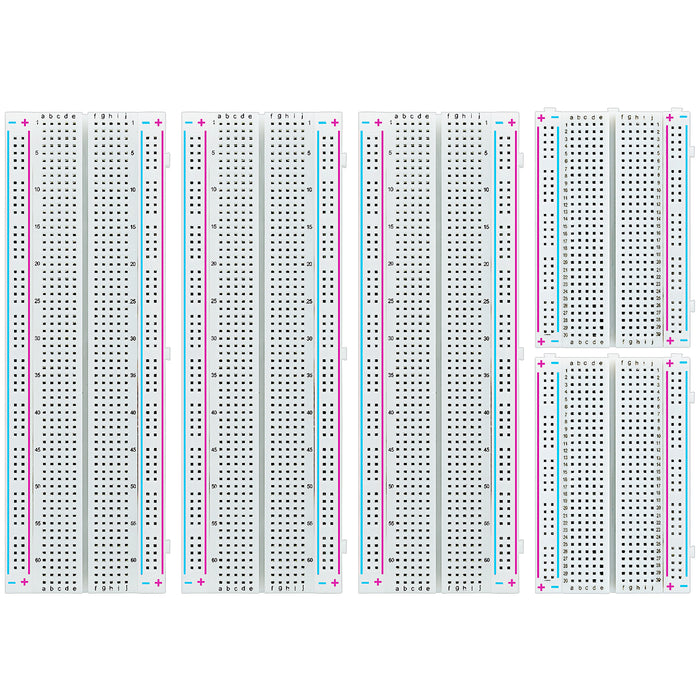
🧱 Breadboards 101 — Solder‑Free Circuit Design
New to electronics? Breadboards let you build and test circuits without soldering. Plug parts in, move things around, learn fast — and keep your desk (mostly) tidy.
💡What is a Breadboard?
A breadboard is a reusable plastic board with lots of tiny holes. Under the holes are metal clips that connect certain holes together. You insert component leads and jumper wires to make quick circuits — perfect for prototyping and learning.
🧬Breadboard Anatomy
Power Rails
Long columns along the sides, usually marked + (red) and − (blue/black). All holes in each column are connected vertically.
Terminal Strips
The main middle area. Holes are connected in short rows of five on each side of the center gap.
Center Gap
A channel that fits IC chips (e.g., timers, microcontrollers). The gap keeps the two sides separate so each IC pin is isolated.
🔌How the Holes Connect
Top view (typical half-size board)
┌────────────── Power Rail (+) ──────────────┐
│  +  +  +  +  +  +  +  +  +  +  +  +  +    │
│  -  -  -  -  -  -  -  -  -  -  -  -  -    │  ⇦ Power Rail (−)
├────────────────────────────────────────────┤
│ a1 a2 a3 a4 a5  |  b1 b2 b3 b4 b5        │  ⇦ Rows of 5 are connected
│ a6 a7 a8 a9 a10 |  b6 b7 b8 b9 b10        │
│ ...             |  ...                    │
├─────────────────┴──────────────────────────┤  ⇦ Center gap (IC channel)
│ c1 c2 c3 c4 c5  |  d1 d2 d3 d4 d5         │
│ ...             |  ...                    │
└────────────────────────────────────────────┘
Each short row (5 holes) is connected internally. The left and right sides are separated by the center gap.
🚦Your First Circuit: LED + Resistor
- Connect the − (GND) of your power source to a − rail. Connect +5V to a + rail.
- Place an LED on the terminal strip so its two legs land in different rows. Long leg = anode (+).
- Put a 220 Ω resistor from the LED’s short leg (cathode) to the − rail.
- Use a jumper from the LED’s long leg to the + rail. Done — it should light!
🧩Sizes & Accessories
🚫Common Breadboard Mistakes
- Putting both LED legs in the same connected row (shorts it out).
- Forgetting to connect the ground of different power sources together.
- Assuming power rails are continuous when they’re split in the middle.
- Using loose or ultra‑thin wires that don’t make solid contact.
🎯Best Practices
- Color code jumpers: red = +, black = −, others for signals.
- Route wires flat and short for reliability and readability.
- Label rails if you use multiple voltages (e.g., 3.3 V and 5 V).
- Test step‑by‑step. Add one connection, power up, verify, repeat.
❓FAQ
Can I reuse a breadboard forever?
They last a long time, but clips wear out if bent or used with oversized leads. If connections get flaky, replace the board.
Why doesn’t my circuit work on the breadboard?
Check row/rail connections, ensure grounds are shared, and use fresh jumpers. A quick continuity test with a multimeter helps.
Can I run motors from breadboard rails?
It’s better to keep motors on a separate supply and use proper driver boards. Share ground, but avoid pulling heavy current through the breadboard.
